Call of Duty 5: SP - Navigation Overview

Overview
Nodes are placed in Radiant and serve several purposes:
• To define spaces that can be navigated by AI (pathnodes)
• To define locations where the AI can take cover (covernodes)
• To define locations where an AI will play an animation or other scripted event (scripted nodes)
• To define areas where the AI can navigate (traverse) a specific obstacle or space (negotiation nodes)
Types Of Nodes
Path Nodes
Place pathnodes at regular intervals (128 units) throughout the map to define the areas where the AI can navigate. For example, if an AI wishes to navigate to a cover_crouch node 500 units away to take cover, there will need to be enough node_pathnodes between himself and the destination, otherwise there will be console errors warning you that he cannot successfully navigate.
Example
1. Place the nodes: Right click in the orthographic view pane and select "node --> pathnode". Place pathnodes at regular intervals (128 units) throughout the map and ensure they do not overlap with any other nodes.
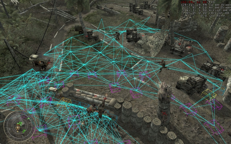
2. Test Node Placement: Ensure that the "connect paths" checkbox is selected in CoDWaW Compile Tools, hit the "compile bsp" button. When the map is loaded, bring down the console and type ai_shownodes 1, then fly around the map (type ufo in the console) to see if all of the paths are properly connected (see picture at the very top). Examine the cyan colored navigation mesh that has been created, and look for red "X" marks which indicate a node that the AI cannot reach. To view more of the mesh at a time, type ai_shownodesdist 1024 (or some other high number). To view colored boxes to represent node types, type ai_shownodes 64.
3. Refine Node Placement: Add or remove nodes to make an efficient navigation mesh. For nodes that appear as red "X" marks, it usually means there needs to be one or more pathnodes added to reach it, or it is in an inaccessible location. If the node in question is behind a barrier or on an elevated shelf where the AI would need to climb, it may require the use of a negotiation node (traverse) prefab (explained below).
Cover Nodes

Cover Nodes will be used to define locations where friendly and enemy AI will try to take cover. Place nodes in Radiant by doing the following:
Example
1. Place the node: right click in the orthographic view pane and select "node --> cover --> <type_of_node>". Deciding the type of cover node depends on the geometry where the node is placed (discussed below).
2. Snap to grid: it is usually good practice to make sure the node is snapped to the grid, especially if the node needs to be flush against geometry that is on the grid. Select the node and hit "ctrl + g" to snap it to whatever grid you have selected.
3. Point in a direction: select the node and give it a direction using the angles buttons on the entity pane (shortcut: n) or rotate the node using the shortcut “shift + d”. The node should be pointing in the direction of the cover geometry itself.
4. Preview: You can preview roughly how the AI will look at the node by cycling through the "cycle preview model" button in the top right of the icon toolbar at the top of Radiant.
5. Set special properties (optional): In the case of certain cover nodes such as cover_left and cover_right, the designer can specify that the AI will only stand or crouch at the node by selecting ticking the DONT_STAND or DONT_CROUCH checkboxes in the entity property pane.
Cover Types
node_cover_crouch - AI will lean and crouch against this cover and pop up to engage enemies. Place cover_crouch nodes flush against the surface behind which the AI will take cover and rotate to point in the direction of the cover geometry. 36 units high is a good standard height for this type of cover to ensure the AI is concealed but can still fire over it effectively.
node_cover_stand - AI will lean against this cover and pop up to engage enemies. Place this node flush against the surface behind which the AI will take cover and rotate to point in the direction of the cover geometry. 48 units high is a good standard height for this standing cover to ensure the AI is concealed but can still fire over it effectively.
node_cover_prone - AI will lay prone and engage enemies. Place this node on relatively flat surfaces and rotate in the direction where the AI will fire.
node_cover_right/left - Used for standing cover where the AI will strafe out from behind to engage enemies. Useful for doorways and corners. The "right" and "left" refer to which direction the AI will strafe out to reveal themselves as they engage the enemy. Facing a doorframe, for example, a node_cover_right would be placed on the left side of the door frame. Place this node flush against the surface behind which the AI will take cover and rotate to point in the direction of the cover geometry.
Traverse Nodes
There are several prefabs that contain pre-made negotiation node combinations and settings that are to be used for specific AI navigation requirements such as hopping over a low wall, sliding over a car, jumping off a ledge, etc. These prefabs can be found in \map_source\prefabs\traverse.
Example
1. Select traverse prefab: Right clicking in the orthographic view pane and select "misc --> prefabs". In the dialog box, navigate to \map_source\prefabs\traverse and select an appropriate traverse prefab.
2. Place prefab: Place the prefab on the geometry/obstacle. Be sure to rotate the prefab in the direction in which the AI should approach it (the arrows on the negotiation nodes point in the direction the AI will execute the traverse). Ensure there are enough path nodes to allow AI to navigate to the traverse.
