Call of Duty 4: Toolbar
By Peri
![]() This tutorial describes the Radiant Toolbar. It is not complete but near enough :)
This tutorial describes the Radiant Toolbar. It is not complete but near enough :)
Radiant can look pretty confusing when seen for the first time. Don't let this put you off. Most of radiants more useful functions are easily found on the toolbar. Although there are more options hidden away as menu items (and even a few that can only be found if you know the keyboard shortcuts), if you know the toolbar you know enough to get mapping.
File Tools
Open a file (map), or save your work.
Transpose (Flip or Mirror) Tools
This will take your selected object and flip (or mirror if you prefer) in one of the 3 axis. Imagine X axis as North-South, Y axis as East-West and Z axis as Up-Down. NB. If you flip a patch, and find out its now textured on the wrong side, keep it selected and goto the patch menu -> invert. This will swap the 'textured' side and the 'blank' side
Rotate Tools
Similar to the transpose tools, except these rotate an object in any one of three dimensions, in 90 degree steps.
Selection Tools
Complete Tall, Select Touching, Partial Tall, Inside.
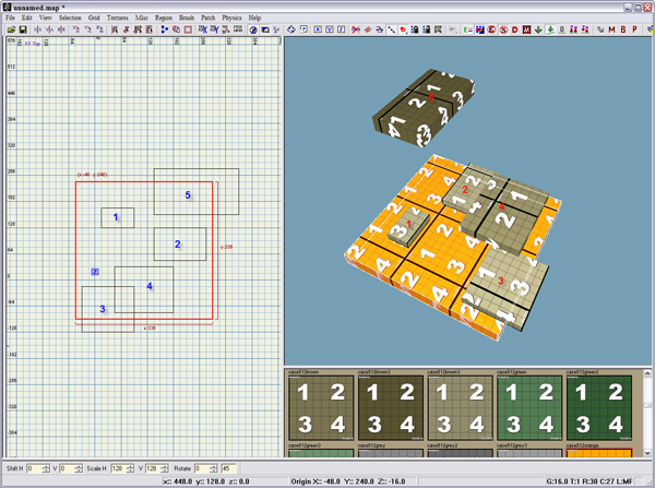
Whilst its possible to select each object individually, sometimes its desirable to select a whole heap of objects (models, brushes, patches etc etc)at once. Maybe you need to select everything that makes up a house, or maybe you have a map problem and you want to select the entire right hand side of the map. Thats where these tools come in. Firstly, in the 2d window draw a brush around the objects you want to select (Yellow in the picture - the texture of the brush isn't important.)
- Complete Tall
This will 'extend' the brush you drew in the 2d window both towards you and away from you making a square tube or tunnel that runs right through your map, from one side to the other (or top to bottom, depending on the 2d view).Anything that is completely inside this 'tube' will be selected, and the tube will dissapear. In the above picture brushes 1,2 and 4 would be selected
- Partial Tall
Works exactly the same as above, except any object inside or touching the 'virtual tube' gets selected. In the example, all brushes would be selected
- Select Touching
Only objects that are inside or touching the original brush get selected. Radiant doesn't extend your 'selection brush'. In the example brushes 1,2 and 3 would be selected, as they are touching the yellow brush. (Difficult to see, i know)
- Select Inside
This will select just the brushes that are inside the 'selection brush'. In the example, non of the brushes would be selected. This method is basically putting a box around objects - only those items totally inside the box (in X,Y and Z) get selected.
 Instead of using these buttons, right clicking in the 2d window will give you a menu where the 'select'
options are the top most item.
Clipper Tool
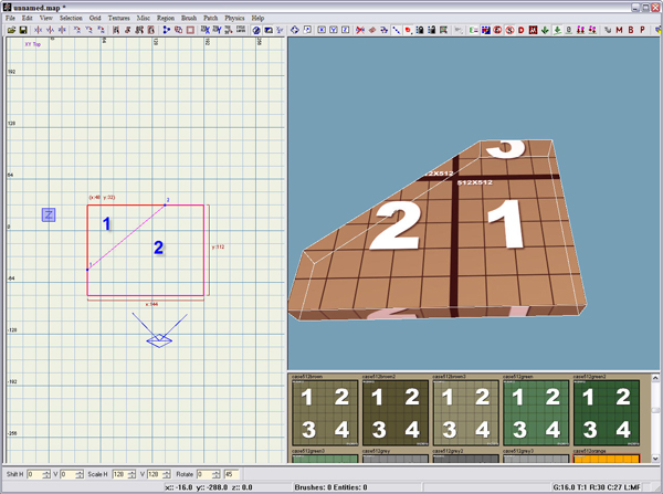
One of the most important modeling tools in your arsenal. Its used for breaking up brushes into smaller pieces, for cutting windows and doors, trimming geometry and 100's of other things. I'd actually recommend learning the keyboard shortcut for this (ctrl+right mouse button), as its much quicker than toggling the button everytime you need to cut something. To use it, simply select a brush (this tool only works on brushes). Ctrl+RHB to mark the first point, and ctrl+rhb to mark the second point. You can actually do 3 point clipping, but thats a more advanced skill.
You'll notice that although the 3d window shows the brush as now having lost a piece, the 2d window still shows the complete brush.
You now have 3 options :
- Hit 'enter' and you'll complete the cutting process. The brush will be as it is in the example.
- Press 'ctrl+enter' - the pieces in the 3d window will reverse. The missing piece will re-appear, and the piece you can see will vanish.
- Press 'shift+enter' and both pieces will appear. It'll still look like a single brush, but actually its 2 pieces.
 Time saving tip. If you are clipping to remove a part of a brush you can work in a clockwise direction so as
to keep the correct piece after the cut rather than having to press 'shift or ctrl+enter' to restore the other part.
As in the example image, where point 1 was placed at '9 o'clock' and point 2 was placed at '12 o'clock', removing the top left corner of the brush (segment 1).
CSG Tools
CSG Merge, CSG Hollow
Firstly, a word of warning. Many mappers believe CSG features to be tools of the Devil, avoided at all costs, just waiting for a chance to ruin your work. Others have used them and never had any problems. Use them at your discretion.
- CSG Merge - used to join 2 brush pieces back into a single brush. There are a few restrictions. The 2 pieces must have a shared edge, and be the same thickness. In the last example, the 2 pieces that resulted after we cut the brush could be joined. If either of the pieces was altered in any way, the merge would fail.
- CSG Hollow - used to hollow out a brush. Used mainly by most people to make a quick and dirty skybox. Easiest way of thinking about this tool is that it will turn a solid block into a hollow box - from a cube with 6 faces into a box with 6 brush sides. The 'thickness' of the 'sides' depends on the size of the grid before hollow is pressed.
Texture Manipulation Tools
Tex flip X, Tex Flip Y, Tex Rotate 90degrees, Cycle Texture Layer
Fairly straightforward. The first two will flip a texture in either the X or Y axis. For example, if you have a door and the hinges of the texture you want to use are on the wrong side, use these to swap the left and right hand sides over.
Next is a button that will rotate a texture through 90 degrees - not much more to say about that one.
- Cycle Layer Texture - Radiant actually has 3 'modes'. The first is the texturing mode, this is what radiant starts in, and what everyone knows. It also has a 'lightmap' mode, where alterations to the amount of attention the compiler pays to light interacting with surfaces can be made, and finally a 'smoothing' mode which deals with the way light 'bounces' off surfaces. Clicking this button cycles between these layers.
Camera Tools
Camera Mode 2, Cubic Clipping, Change 2d view
- Camera mode 2 - Changes the way you move around 3d space. (A bit of a nightmare imo :) )
- Toggle Cubic Clipping - No matter how fast your computer is, if your map gets big enough you'll start to encounter fairly serious lag when trying to navigate around the 3d view. Cubic clipping attempts to get round this by not drawing any geometry over a certain distance from where you are working. Use ctrl+[ (decrease) and ctrl+] (increase) to alter the distance that geometry is culled.
- Change 2d view- Does just that. Much, much easier to get into the habit of using the kb shortcut ctrl+tab
Rotate And Scale Tools
Free Rotate, Free Scale.
- Free Rotate - select an object and then, in the 2d window, lmb (left mouse button) click and drag to rotate. The 'smoothness' of the rotation depends on the grid settings. Can be used on multiple objects.
- Free Scale - Same as above, select a brush or patch and in the 2d window lmb click and drag to change the size of the object. When the object is the right size, hit 'escape' to de-select it.
Lock Axis
Lock X, Lock Y, Lock Z
These three tools all work exactly the same, only difference is the axis that they act on. Mainly used to help when moving geometry around your map. If you look down in the 2d view, so your map is in 'plan view', select an object then 'lock X', you'll find the object can only move in Y (ie east and west). Great for when you want to move window frames or ledges from one side of a building to another for example. Lock Y stops movement in the north-south direction, and lock Z stops up-down movement.
Don't Select Curved Patches
This has a misleading name. It actually prevents you from selecting any patches, whether they are curves or terrain.
Show Patches As Wireframes
This cycles between 3 modes. In its first mode you view patches as normal textured meshes. In its second mode, the textures become invisible, and just the triangles that make the patch are shown. In its third mode, you get both effects - Textured patches with the triangles that make it up drawn over the top.
Redisperse Patch Points
Appears to be broken
Weld Equal Patch Points During Moves
Selects Drill Down Rows And Columns
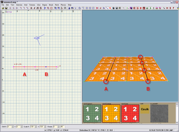
Changes the way selecting vertices in the 2d window affects your patches.
With this disabled, selecting the vertex at point A in the 2d window, results in just 1 vertex being selected. At point B, with it turned on, Radiant selects all the points immediately behind the one you selected.
Lock & Unlock Patch Vertex Tools
These are used for making vertices immobile, and releasing them later.
Imagine you have a terrain patch that you want to make 'bumpy' with the terrain editing tools, but 2 edges are lined up and exactly where you want them - you don't want those edges altered in any way. First, hit the 'Lock' button. Select the verts you want to stay in place - they will turn red. Now hit the 'lock button' again to get out of vertex locking mode. Make all the alterations you need - the red vertices will not move. If you decide later that you need to alter those red verts, hit the 'unlock' button, select the red ones and they will revert to normal. When you've finished hit 'unlock' again to get out of unlocking mode.
Cycle Edge Direction On Terrain Quads
Show Entities As
Changes the way entities are shown in your 3d view. Wireframes, big boxes, normal etc etc. Probably best left as normal (skinned)
Toggle Alpha Rendering Of Textures
![]() Show/Dont show Alpha Blending on Patch in 3D View
Show/Dont show Alpha Blending on Patch in 3D View
Disable Selection Of Entities
Prevents you from selecting entities in your map.
Disable Selection Of Skybrushes
Prevents you from selecting skybrushes. A very useful tool!
Toggle Drawing Of Draw Toggle Surfs
Unsure what that does...
Toggle If Models Are Selectable
Prevents you from selecting models.
Model Planting Tools
Plant Models with random scale and rotation, Orient dropped Selection to the floor, Force Drop height to 0, Drop Selected Entities to floor, Drop Selection with Relative Z Heights
- These tools are used to easily fit models (be it a single truck, or 30 different grass clumps) into your landscape. The first 3 buttons change what happens when you click the 4th or 5th button.
- Plant Models with random scale and rotation - This will force Radiant to apply a random scale and rotation to the models. Great for making tufts of grass look different, not so useful if you are placing a model truck. (The base size and amount of scaling allowed can be set in the prefs under 'Scale Base' and 'Scale Range')
- Orient dropped Selection to the floor - Normally left turned on. This will make the model 'follow' your terrain. If you are placing a truck on a hill, this ensures the truck actually slopes up or down the hill, and that it isn't horizontal with the back wheels embedded in the hill and the front wheels in mid air.
- Force Drop height to 0 - Normally left turned on. This will make your model actually 'sit' on the ground. Turning it off will make the model float in the air a set distance above the ground. (This distance can be altered in the preferences under 'drop height')
- Drop Selected Entities to floor - Once you have the previous 3 buttons toggled how you want, this is the one that will actually move your models to the floor
- Drop Selection with Relative Z Heights - Exactly the same as above, except if there are any height differences in a group of models, it will preserve them.
 Instead of pressing the purple icon, you can ctrl+alt+click on the ground (copies the currently selected
entity and drops it where you clicked), or ctrl+alt+middle click on the ground (moves the currently selected
entity to where you clicked).
Tolerant Weld
Used for altering what happens when you 'weld' vertices together with the 'W' key. Selecting this tool means that you wont be welding a vertice thats miles away in the background. Useful when welding from 3D view.
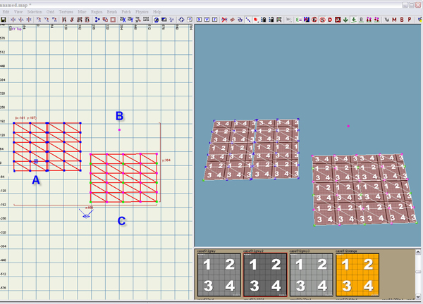
Normally, selecting any 2 or more vertices and pressing W to weld them results in all the verts combining at a single spot. At A there are 2 patches with a small gap between them. Selecting all the verts and pressing W results in B - all vertices are welded together.
With tolerant weld enabled only vertices within a specified distance weld together. Doing exactly the same as above results in C - only the vertices close to each other get welded.
You can alter the distance that tolerant weld works at in the preferences under (surprisingly) 'Tolerant Weld'
Unknown
Cycle Preview Model
Sources
Thanks to Peri for sharing!


